|
|
Marking the Rotation Cuts |
|
|---|

|
|
|
The philtral unit requires symmetrical philtral columns. Another common technical error in R-A repairs is the surgeon's failure to make the rotation scar mimic the opposite, normal philtral column.
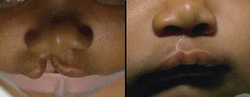
Fig. 27 shows two examples of rotation scars that are too straight. |
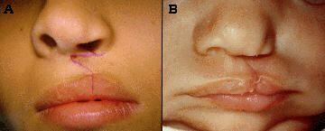
Fig. 27 |
|
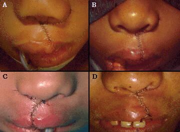
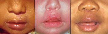
Fig. 28 shows four examples of rotation scars that are too curved. In all of the above cases the philtral columns are asymmetric. Not one of these patients has a normal looking philtrum. |
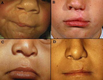
Fig. 28 |
|
Fig. 29A shows a rotation cut with too much curve, retaining too much tissue at its junction with the columellar crease. The remaining intra-op and post-op views clearly demonstrate how this unsatisfactory result was predetermined by, and could be predicted from, the pre-op markings. How can one plan the rotation cut so it will always match the normal ridge? First, plot the normal philtral column on the non-cleft side, noting its curvilinear course. When drawing the rotation cut on the cleft side, match that same curve from the high point of cupid's bow up to the labio-columellar crease. From this point, the rotation incision is continued in the labio-columellar crease. |
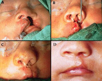
Fig. 29 |
|
Sometimes this line utilizes the entire labio-columellar crease (Fig.30A and B); other times it may reach this crease closer to the mid-line of the columella (Fig.30C); rarely, it may not reach this crease until one approaches the non-cleft side of the columella (Fig.30D). Wherever this line meets the naso-columellar crease, it then continues in the crease to a point just proximal to the normal philtral column, the sight of the cut-back as described by Millard2, 10, 12. When one does this, the philtral unit symmetry is immediately obvious in the pre-op markings. |
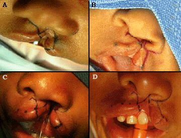
Fig. 30 |
|
The immediate post-operative appearance (Fig.31 and Fig.32) and later post- operative scars (Fig.33 and Fig.34) confirm the effectiveness of paying careful attention to this anatomic detail: |
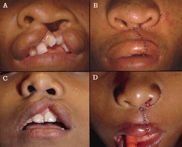
Fig. 31
Fig. 32
Fig. 33
Fig. 34 |
|
|